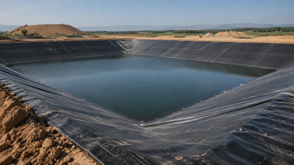
Choosing the right HDPE geomembrane thickness is not simply a matter of buying the thickest liner available.
For commercial and engineered containment projects, commonly considered thicknesses include 0.75 mm, 1.0 mm, 1.5 mm and 2.0 mm, while thinner 0.5 mm liners may also be used in some lighter-duty water-containment applications.
The correct choice depends on more than the application name. Subgrade condition, puncture risk, protection geotextile, loading, chemical exposure, whether the liner is covered or exposed, slope conditions, installation procedures and project specifications can all affect the final selection.
For engineered projects, the approved specification should always take priority over a generic thickness chart.
Key Takeaways
- 0.75 mm, 1.0 mm, 1.5 mm and 2.0 mm are common HDPE geomembrane thickness options for many commercial and engineered applications.
- Project type is useful for establishing a preliminary range, but it should not be the only selection criterion.
- Thicker HDPE generally provides higher force-based tensile, tear and puncture values within the same product series.
- A thicker liner does not eliminate the need for proper subgrade preparation or protective geotextile.
- Landfills, mining facilities and regulated containment projects should follow the approved engineering specification and applicable requirements.
- Welding quality, detailing and installation QA/QC remain critical regardless of membrane thickness.
HDPE Geomembrane Thickness: mm vs Mil vs Micron
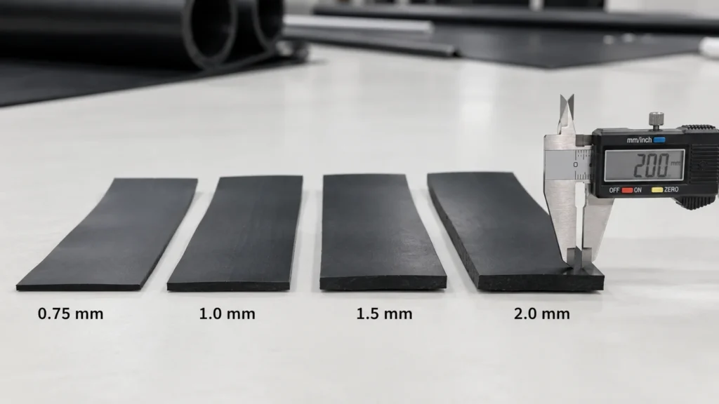
Different markets describe geomembrane thickness using millimeters, mils or microns.
| Nominal Thickness | Approx. Mil | Micron |
|---|---|---|
| 0.50 mm | 20 mil | 500 micron |
| 0.75 mm | 30 mil | 750 micron |
| 1.00 mm | 40 mil | 1,000 micron |
| 1.50 mm | 60 mil | 1,500 micron |
| 2.00 mm | 80 mil | 2,000 micron |
| 2.50 mm | 100 mil | 2,500 micron |
| 3.00 mm | 120 mil | 3,000 micron |
This conversion is especially useful when comparing specifications from different countries.
For example:
1.0 mm HDPE geomembrane ≈ 40 mil
and:
1.5 mm HDPE geomembrane ≈ 60 mil
However, thickness equivalence does not mean two products are technically identical. Resin formulation, density, stress-crack resistance, carbon-black dispersion, oxidation resistance and manufacturing quality should also be checked.
Compare Available HDPE Geomembrane Thicknesses
If you have narrowed your project to 0.75 mm, 1.0 mm, 1.5 mm or 2.0 mm HDPE, the next step is to compare the available specifications, roll sizes and technical data. View our HDPE geomembrane products to review material options for pond, reservoir, wastewater, mining and environmental containment projects.
Check the Project Specification Before Choosing Thickness
Before using any application table, first determine whether the project already has an engineering specification.
For engineered containment, the specification may define:
- geomembrane material;
- nominal thickness;
- smooth or textured surface;
- required physical properties;
- testing methods;
- welding requirements;
- protection layers;
- field quality-control procedures.
If these requirements are already defined, they take priority over general online thickness recommendations.
A generic thickness guide is more useful during:
- preliminary material selection;
- project budgeting;
- supplier comparison;
- quotation preparation;
- early-stage system planning.
It should not replace project-specific engineering design.
Engineering Note
The fact that a particular thickness is commonly used in one application does not mean it is automatically suitable for every project in that category.
Two reservoirs, for example, may have completely different subgrade conditions, slopes, cover systems and service environments.
Quick HDPE Geomembrane Thickness Selection Table
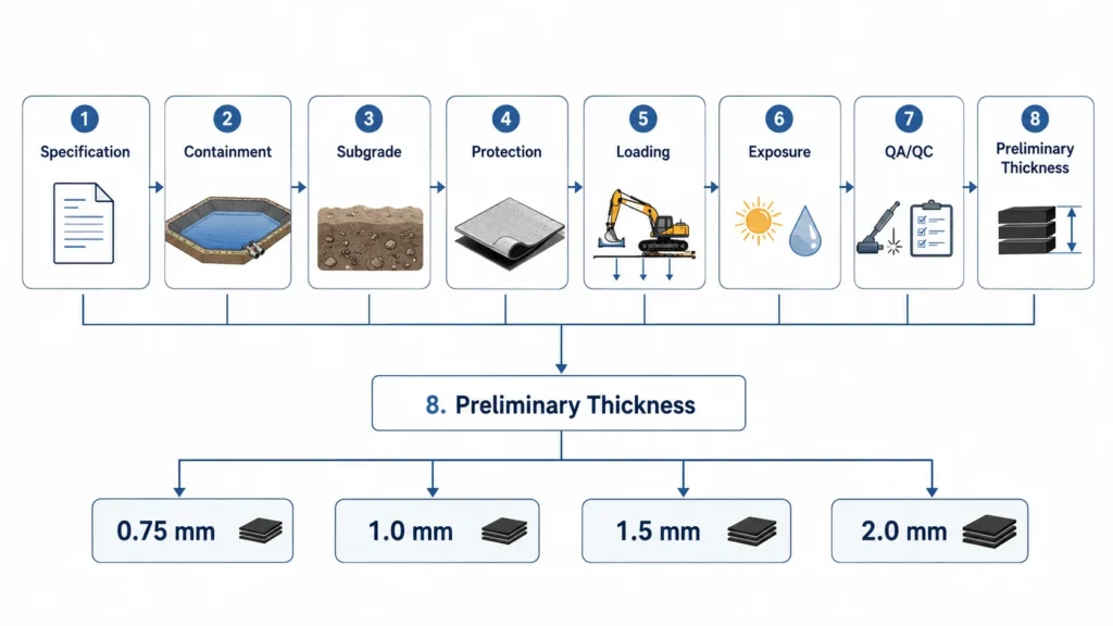
The following ranges should be treated as preliminary reference ranges rather than fixed design specifications.
| Application | Preliminary Range Often Considered | What May Change the Selection |
|---|---|---|
| Small agricultural water pond | 0.5–0.75 mm | Subgrade, puncture risk, exposure, maintenance |
| Aquaculture / irrigation pond | 0.75–1.0 mm | Pond size, slope, protection, installation |
| Reservoir / water storage | 1.0–1.5 mm | Foundation, slope, exposure, anchorage |
| Canal lining | 1.0–1.5 mm | Subgrade, abrasion, cover, deformation |
| Wastewater containment | 1.0–1.5 mm or project-specific | Chemistry, temperature, QA/QC |
| Industrial containment | 1.0–2.0 mm or project-specific | Chemicals, loading, secondary protection |
| Mining containment | Project-specific, often heavier-duty | Aggregate, chemicals, loads, slope |
| Landfill liner system | Commonly 1.5–2.0 mm or project-specified | Regulation, leachate, protection, settlement |
The purpose of this table is to help narrow the initial selection.
The next step is to evaluate why the project may need to move from one thickness to another.
Once these project conditions are clear, you can compare suitable membrane thicknesses, roll sizes and available technical specifications before requesting a quotation. See our HDPE geomembrane product range for available options, or send us your project specification for product-selection support.
What Actually Determines HDPE Geomembrane Thickness?
1. Subgrade Condition and Puncture Risk
Subgrade condition is one of the most important factors in geomembrane selection.
A geomembrane installed over smooth, compacted fine soil experiences a very different contact condition from one installed over:
- sharp stones;
- angular gravel;
- roots;
- construction debris;
- salt crystals;
- waste rock;
- uneven ground.
In mining applications, for example, angular waste rock or crystalline material can create significant localized contact stresses.
The mining geomembrane technical material in our reference library specifically identifies sharp salt crystals and angular mining waste as puncture risks and notes that additional geotextile or protective layers may be necessary in demanding conditions.
This illustrates an important principle:
Thickness should not be used as the only response to a poor subgrade.
Subgrade improvement and protection should be evaluated first.
2. Should You Use a Thicker Liner or Protective Geotextile?
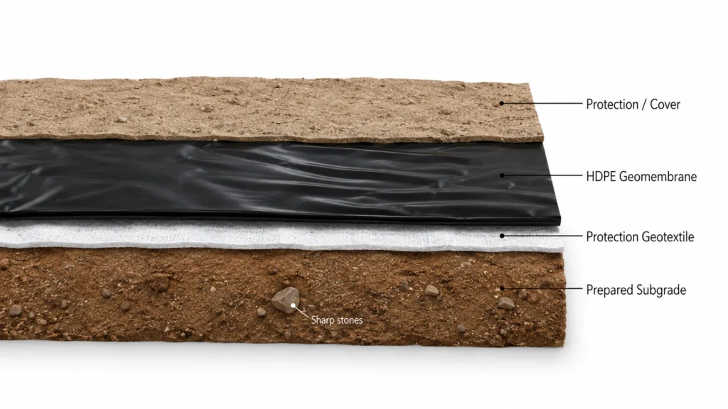
If puncture risk comes from angular stones, coarse aggregate or an irregular foundation, simply increasing membrane thickness may not fully address the source of the problem.
A more complete system may include:
Prepared Subgrade
↓
Protection Geotextile
↓
HDPE Geomembrane
↓
Protection / Drainage / Cover Layer where required
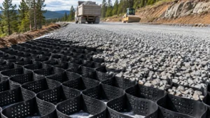
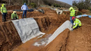
A protective nonwoven geotextile can help reduce localized contact stresses between the geomembrane and rough materials.
This does not mean that geotextile always allows a thinner liner.
It means that:
geomembrane thickness and puncture protection should be considered as parts of the same lining system.
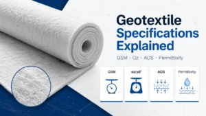
The required geotextile should also be selected according to the actual loading and contact materials. GSM alone should not be treated as a universal protection rule.
3. Mechanical Loading
Geomembranes can experience mechanical stress during both installation and service.
Potential loading sources include:
- cover soil;
- drainage aggregate;
- water pressure;
- construction equipment;
- waste placement;
- settlement;
- irregular support;
- maintenance activity.
A thicker geomembrane generally contains more material per unit area and can provide greater resistance to certain mechanical damage.
However, thickness should still be evaluated together with the complete system.
A deep reservoir, for example, should not be specified only according to water depth. Foundation condition, slopes, deformation, anchorage and liner protection may also affect the design.
4. Chemical Exposure
HDPE geomembrane is widely used for environmental containment because properly formulated HDPE provides resistance to many chemical environments.
But thickness should never be used as a substitute for chemical-compatibility evaluation.
For applications such as:
- industrial wastewater;
- mining process solutions;
- landfill leachate;
- saline water;
- acidic or alkaline liquids;
the project should consider:
- chemical composition;
- concentration;
- temperature;
- continuous or intermittent exposure;
- product formulation;
- applicable compatibility requirements.
A 2.0 mm liner is thicker than a 1.0 mm liner, but that alone does not prove compatibility with every contained chemical.
5. Exposed vs Covered Installation
An exposed geomembrane and a covered geomembrane experience different risks.
Exposed liner
May experience:
- UV exposure;
- temperature cycling;
- wind;
- surface traffic or maintenance;
- exposed mechanical damage.
Covered liner
May experience:
- cover-soil placement;
- aggregate contact;
- installation damage;
- settlement;
- interface stresses.
Therefore, two projects containing the same liquid may still require different liner systems depending on whether the membrane remains exposed.
6. Slope and Site Geometry
Slope conditions influence deployment, anchoring and installation.
Long or steep slopes may introduce additional concerns related to:
- panel handling;
- wrinkles;
- anchorage;
- interface behavior;
- equipment access;
- welding;
- construction sequence.
Thickness alone does not solve these issues.
For demanding slopes, the geomembrane must be evaluated as part of the complete containment structure.
7. Seam Welding and Installation QA/QC
A thicker HDPE geomembrane does not compensate for poor field welding.
Installed containment performance also depends on:
- panel deployment;
- seam preparation;
- trial seams;
- welding conditions;
- field seam testing;
- penetration details;
- repairs;
- installation quality assurance.
Large or regulated containment projects should follow the approved installation specification and QA/QC plan.
This article focuses on thickness selection. Detailed welding procedures should be addressed separately in an HDPE geomembrane installation and welding guide.
0.5mm vs 0.75mm vs 1.0mm vs 1.5mm vs 2.0mm HDPE Geomembrane
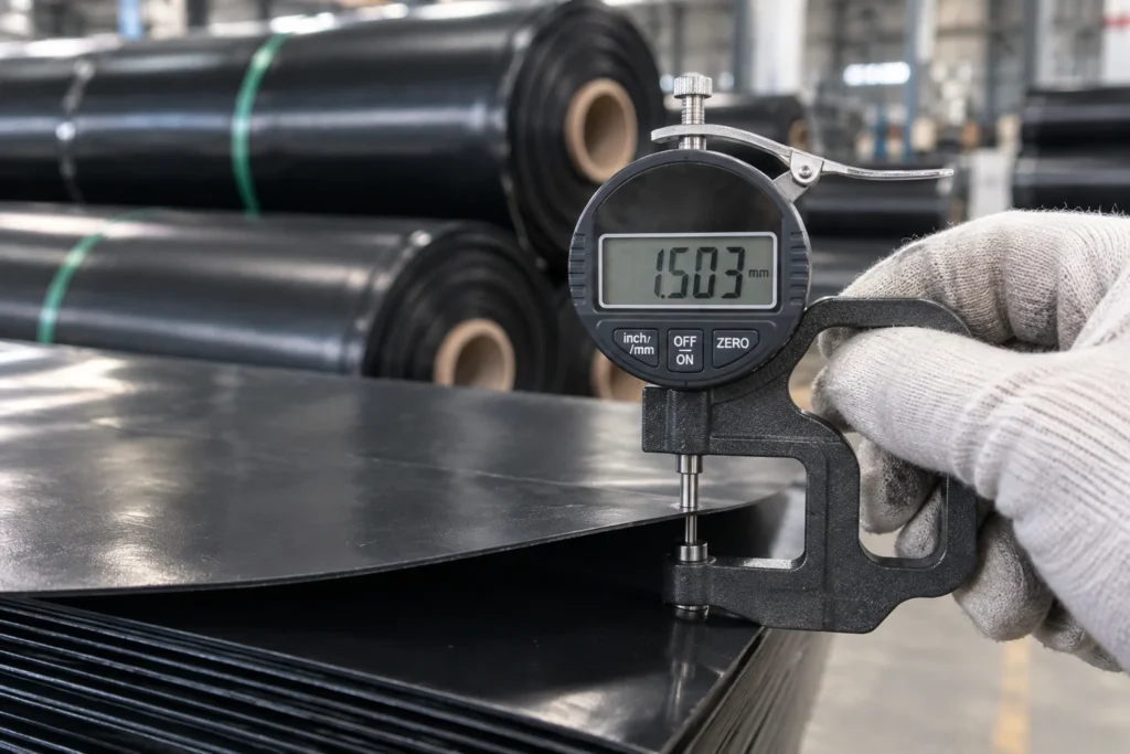
0.5 mm HDPE Geomembrane
0.5 mm, approximately 20 mil, is at the lighter end of HDPE lining products.
It may be considered for some:
- small agricultural ponds;
- temporary or relatively low-risk water containment;
- carefully prepared foundations.
Advantages
- lower material weight;
- easier handling;
- lower material consumption.
Limitations
It provides less mechanical margin against puncture and installation damage than heavier liners.
Subgrade preparation therefore becomes particularly important.
For projects requiring a specific international geomembrane specification, the relevant specification scope should also be checked rather than assuming every thin polyethylene liner meets the same requirements.
0.75 mm HDPE Geomembrane
0.75 mm, approximately 30 mil, is widely encountered in commercial water-containment applications.
Potential uses include:
- aquaculture;
- irrigation ponds;
- agricultural reservoirs;
- selected water-containment systems.
It offers more mechanical robustness than thinner liner products while remaining relatively easy to handle.
However, sharp subgrade materials or demanding loading conditions may still require additional protection or a heavier liner.
1.0 mm HDPE Geomembrane
1.0 mm corresponds to approximately 40 mil.
This thickness is often considered for:
- commercial ponds;
- irrigation reservoirs;
- water storage;
- canal lining;
- selected wastewater systems;
- secondary containment.
It represents a practical middle range between lighter pond liners and heavier engineered geomembranes.
But it should not be interpreted as a universal specification for ponds.
A rocky excavation or industrial containment project may require a different approach even if 1.0 mm is commonly used in other projects.
1.5 mm HDPE Geomembrane
1.5 mm corresponds to approximately 60 mil.
It is commonly considered for more demanding containment systems, such as:
- large reservoirs;
- wastewater ponds;
- industrial containment;
- mining applications;
- selected landfill liner systems where specified.
Compared with 1.0 mm material from the same product series, 1.5 mm generally provides higher force-based tensile, tear and puncture values.
However, it still requires:
- proper subgrade preparation;
- protection where needed;
- controlled installation;
- reliable seam welding.
2.0 mm HDPE Geomembrane
2.0 mm corresponds to approximately 80 mil.
This heavier geomembrane may be considered for demanding engineered applications such as:
- landfill containment;
- mining;
- industrial containment;
- waste containment;
- high mechanical-risk environments.
The additional thickness increases material use and roll weight and can make handling more demanding.
Therefore:
2.0 mm should be selected because the project requires it—not simply because it is the thickest common option.
How Does Thickness Affect Measured Mechanical Properties?
This is where thickness becomes easier to understand using real product data.
The following values come from a mining-grade HDPE geomembrane reference product series covering 0.75, 1.0, 1.5 and 2.0 mm nominal thicknesses.
The source lists ASTM D5199 for thickness, ASTM D6693 for tensile properties, ASTM D1004 for tear resistance and ASTM D4833 for puncture resistance.
Reference HDPE Geomembrane Test Data by Thickness
| Nominal Thickness | Tensile Yield Strength | Tensile Break Strength | Tear Resistance | Puncture Resistance |
|---|---|---|---|---|
| 0.75 mm | 16 N/mm | 27 N/mm | 120 N | 350 N |
| 1.0 mm | 18 N/mm | 32 N/mm | 150 N | 480 N |
| 1.5 mm | 25 N/mm | 46 N/mm | 220 N | 650 N |
| 2.0 mm | 40 N/mm | 62 N/mm | 300 N | 800 N |
The same reference product series reports a density of approximately 0.943 g/cm³, yield elongation of 12%, break elongation of 750%, stress-crack resistance of 300 h, carbon-black content of 2.25%, standard OIT of 120 min and high-pressure OIT of 430 min across these four thicknesses.
What Does This Data Tell Us?
Within this product series, increasing nominal thickness is associated with higher:
- tensile force per unit width;
- tear resistance;
- puncture resistance.
For example, the listed puncture resistance increases from:
350 N at 0.75 mm
to:
800 N at 2.0 mm.
However, this table must be interpreted correctly.
It shows the behavior of one specific reference product series under the listed test methods.
It does not mean:
“800 N puncture resistance automatically makes 2.0 mm correct for a landfill.”
Nor does it mean every manufacturer’s 1.5 mm geomembrane has identical values.
Engineering Note
Laboratory data helps compare material properties.
Project selection must still consider:
specification + subgrade + loading + protection + chemical exposure + installation.
For a deeper explanation of yield strength, break strength, elongation and testing, see our guide to HDPE Geomembrane Properties, Standards and Tensile Strength.
40 Mil vs 60 Mil HDPE Liner: Which Should You Choose?
1.0 mm and 1.5 mm are among the most commonly compared HDPE geomembrane thicknesses.
| Factor | 40 Mil / 1.0 mm | 60 Mil / 1.5 mm |
|---|---|---|
| Material quantity | Lower | Higher |
| Roll weight | Lower | Higher |
| Handling | Generally easier | More demanding |
| Relative puncture robustness | Lower | Higher |
| Relative tear resistance | Lower | Higher |
| Typical positioning | Moderate containment | More demanding containment |
| Pond / reservoir use | Common where conditions suit | Often considered for higher-risk conditions |
| Waste / industrial applications | Project-dependent | More commonly considered |
| Cost | Lower | Higher |
The right question is not:
“Is 60 mil better than 40 mil?”
Instead ask:
What risk is the additional thickness intended to control?
If puncture comes from angular aggregate, protection may be required.
If chemical exposure is the main concern, compatibility should be evaluated.
If a project specification already requires 60 mil, that requirement takes priority.
If the site is a simple prepared water pond, 60 mil may provide additional robustness but may not always be necessary.
HDPE Geomembrane Thickness by Application
Pond and Agricultural Water Containment
For lighter pond projects, thicknesses around 0.5–1.0 mm are commonly considered as preliminary options.
The appropriate range depends heavily on:
- pond size;
- foundation quality;
- roots or stones;
- slope;
- exposure;
- maintenance access;
- protection requirements.
A smooth compacted agricultural pond and a rocky excavated pond should not automatically use the same liner thickness.
For larger reservoirs or higher-risk water-containment systems, heavier options may be considered.
If liner material itself is still being selected, see our Best Pond Liner Guide.
Aquaculture and Irrigation Ponds
Aquaculture projects often cover large areas, so material cost is an important consideration.
However, selecting the thinnest possible membrane can create additional installation risk if the pond base is poorly prepared.
Common considerations include:
- soil preparation;
- slopes;
- equipment access;
- liner exposure;
- cleaning and maintenance;
- expected operating conditions.
A 0.75 or 1.0 mm liner may be considered in many commercial pond systems, but final selection should follow actual site conditions.
Reservoirs and Water Storage
Larger reservoirs introduce different challenges from small ponds.
These may include:
- larger panel areas;
- long slopes;
- anchorage;
- foundation movement;
- exposure;
- more complex installation.
A preliminary range around 1.0–1.5 mm may be considered for many water-storage projects, while demanding engineered systems may use other specifications.
Thickness should be evaluated together with foundation and protection requirements.
Canal Lining
HDPE geomembrane used in canals may be exposed to:
- irregular subgrade;
- slope conditions;
- erosion;
- maintenance activity;
- deformation;
- cover systems.
Thicknesses around 1.0–1.5 mm may be considered during preliminary selection, but canal design cannot be reduced to thickness alone.
Where concrete, soil or other protective cover is used, the interaction between layers should also be considered.
Wastewater and Industrial Containment
Wastewater applications require more than simple waterproofing.
The selection process may need to consider:
- chemical composition;
- temperature;
- sludge or solids;
- maintenance;
- subgrade;
- cover system;
- regulatory requirements.
For this reason, 1.0–1.5 mm or heavier geomembrane may be considered depending on the application, but no single thickness should be presented as universally correct.
Landfill Liner Systems
Landfill liners are engineered systems and should not be selected from a generic online application chart.
A landfill lining system may need to consider:
- applicable environmental requirements;
- waste type;
- liner function;
- leachate;
- foundation settlement;
- drainage;
- geotextile protection;
- GCL or other components;
- field QA/QC.
Thicknesses around 1.5–2.0 mm are commonly encountered in engineered landfill applications, but the approved project specification determines the final requirement.
Avoid statements such as:
“All landfills require 2 mm HDPE.”
That is too absolute.
Mining Containment
Mining is another application where project conditions vary widely.
A tailings pond, heap-leach facility, process-water pond and saline evaporation pond do not create identical loading or chemical conditions.
Mining-related selection may need to consider:
- angular rock;
- salt crystals;
- chemical exposure;
- acidic or alkaline liquids;
- heavy construction;
- slopes;
- drainage;
- liner protection.
The mining-grade membrane reference material used in this article specifically identifies salt corrosion, acidic/alkaline media and puncture from sharp salt crystals or waste rock as major application concerns.
These conditions demonstrate why mining geomembrane selection should not rely on thickness alone.
Thickness Is Only One Part of the Lining System
A reliable containment system is not simply:
HDPE geomembrane
It may consist of:
Prepared Foundation
↓
Protection Geotextile
↓
HDPE Geomembrane
↓
Field-Welded Seams and Details
↓
Drainage / Protection / Cover Layers
The exact configuration depends on the project.
A thicker membrane can improve certain measured mechanical properties, but it cannot correct:
- sharp debris left beneath the liner;
- poorly prepared subgrade;
- inadequate protection;
- defective welding;
- improper anchorage;
- uncontrolled installation damage.
This is why liner selection should be treated as a system decision rather than a thickness-only decision.
Is a Thicker HDPE Geomembrane Always Better?
No.
A thicker liner can provide greater mechanical robustness, but more thickness is not automatically the best engineering or purchasing decision.
Under-Specifying
Choosing a thin membrane only to minimize material price may increase risk where the project has:
- angular subgrade;
- heavy cover;
- construction traffic;
- demanding containment conditions.
Over-Specifying
Using a heavy 2.0 mm liner for every small, well-prepared water pond may increase:
- material consumption;
- freight;
- roll weight;
- handling;
- installation requirements;
without necessarily providing proportional project value.
The objective is not to choose the maximum thickness available.
The objective is to choose a liner system appropriate for the actual conditions.
Common HDPE Geomembrane Thickness Selection Mistakes
1. Selecting by Application Name Alone
“Pond” or “landfill” is not enough information to select a complete specification.
2. Choosing Only by Price
Price matters, but replacing or repairing a damaged lining system can cost far more than the difference between two appropriate material options.
3. Assuming Thicker Is Always Better
A thicker membrane does not automatically solve chemical, foundation, seam or drainage problems.
4. Ignoring the Subgrade
Sharp stones and irregular surfaces can create localized stresses regardless of nominal thickness.
5. Ignoring Protective Geotextile
Where puncture risk exists, the liner and protection layer should be evaluated together.
6. Comparing Thickness Without Comparing TDS Data
Two 1.5 mm membranes should not automatically be assumed to have identical performance characteristics.
Review:
- tensile properties;
- tear;
- puncture;
- stress-crack resistance;
- OIT;
- carbon-black properties;
- applicable test methods.
7. Copying Another Project’s Specification
A specification that worked for one mine, reservoir or landfill may not be appropriate for another site.
8. Ignoring Field Welding
Even a correctly selected membrane can lose containment integrity if seams or details are poorly installed.
Before Requesting a Quote: What Information Should You Provide?
Instead of asking:
“What thickness of HDPE liner do I need?”
provide the supplier with basic project information.
| Information | Why It Matters |
|---|---|
| Project type | Establishes the containment function |
| Total area | Helps determine roll quantity and installation scale |
| Contained liquid or waste | Helps assess chemical conditions |
| Maximum depth | Provides service-condition context |
| Subgrade type | Indicates potential puncture/contact risk |
| Sharp stones or aggregate | May affect protection requirements |
| Slope information | Influences deployment and installation |
| Exposed or covered liner | Changes environmental and mechanical exposure |
| Protective geotextile | Helps define the complete liner system |
| Engineering specification | May already define material requirements |
| Project country/location | Helps identify logistics and applicable requirements |
| Required test standard | Allows more accurate TDS comparison |
The more accurate the project information, the more useful the product recommendation becomes.
A Practical HDPE Geomembrane Thickness Selection Process
Step 1 — Check the Project Specification
If thickness and product requirements are already defined, start there.
Step 2 — Identify the Containment Application
Determine whether the system contains clean water, wastewater, waste, mining liquids or other materials.
Step 3 — Review the Subgrade
Check for stones, aggregate, roots, salt crystals, waste rock or irregular foundation conditions.
Step 4 — Evaluate Protection
Determine whether subgrade improvement or protective geotextile is needed.
Step 5 — Review Loading and Exposure
Consider water depth, cover materials, construction equipment, UV exposure and settlement.
Step 6 — Review Chemical Conditions
For wastewater, industrial and mining projects, confirm that the liner material is appropriate for the expected environment.
Step 7 — Establish a Preliminary Thickness Range
Compare 0.75, 1.0, 1.5 or 2.0 mm based on the actual project conditions.
Step 8 — Compare Current Product TDS
Check test methods and relevant properties rather than nominal thickness alone.
Step 9 — Confirm Installation and QA/QC Requirements
Review seam welding, protection, repairs and field inspection requirements.
Choosing an HDPE Geomembrane for Your Project
For preliminary procurement, the following simplified logic is useful:
Lower-risk water containment
→ thinner options may be sufficient under suitable site conditions.
Higher puncture or mechanical risk
→ consider heavier geomembrane and/or additional protection.
Wastewater or chemical exposure
→ evaluate both membrane properties and compatibility.
Landfill, mining or regulated containment
→ follow the project specification and engineered liner-system requirements.
GeoSynSource supplies HDPE geomembrane options for water containment, ponds, wastewater, mining and environmental projects.
If you are comparing 0.75 mm, 1.0 mm, 1.5 mm or 2.0 mm, send your project conditions or technical specification so the available products can be compared against your actual requirements.
View HDPE Geomembrane Products →
Frequently Asked Questions
How do I choose HDPE geomembrane thickness?
Start with the project specification, then evaluate the application, subgrade, puncture risk, protection layer, mechanical loading, chemical exposure, exposed or covered conditions and installation requirements. Application tables should only be used to establish a preliminary range.
Is 1mm HDPE geomembrane enough for a pond?
A 1.0 mm or approximately 40 mil HDPE liner can be suitable for many pond and water-containment applications, but suitability depends on subgrade, stones or roots, slopes, liner exposure, protection and project requirements.
What is the difference between 40 mil and 60 mil HDPE liner?
40 mil is approximately 1.0 mm, while 60 mil is approximately 1.5 mm. Within the same product series, a 1.5 mm membrane generally has higher force-based tensile, tear and puncture values, but it also uses more material and is heavier to handle.
What HDPE geomembrane thickness is commonly used for landfill liners?
Thicknesses around 1.5–2.0 mm are commonly encountered in engineered landfill liner systems, but landfill requirements are project- and regulation-specific. The approved engineering specification should determine the final membrane requirement.
Is thicker HDPE geomembrane always better?
No. Greater thickness can improve certain mechanical properties, but it cannot correct poor subgrade preparation, unsuitable chemical compatibility, inadequate protection or defective seams.
Should geotextile be installed under an HDPE geomembrane?
A protective geotextile may be appropriate where sharp stones, coarse aggregate or irregular surfaces create puncture risk. The need and required geotextile specification depend on the complete lining system and expected loading.
Does HDPE geomembrane thickness affect puncture resistance?
Within the same product series and test method, thicker HDPE geomembrane commonly shows higher puncture resistance. In the mining-grade reference series used in this article, ASTM D4833 puncture values increased from 350 N at 0.75 mm to 800 N at 2.0 mm. These values are product-specific and should not be treated as universal design values.
Conclusion
HDPE geomembrane thickness should be selected as part of the entire containment system, not as an isolated product parameter.
For many commercial projects, 0.75 mm, 1.0 mm, 1.5 mm and 2.0 mm provide useful starting points for comparison. But the final decision should consider:
project specification + subgrade + puncture protection + loading + chemical exposure + installation + QA/QC.
Thicker HDPE generally provides higher force-based tensile, tear and puncture values within the same product series, but increasing thickness is not a substitute for good foundation preparation, protection or welding.
If your project does not yet have a final membrane specification, send GeoSynSource your application, area, site conditions and required standards so the available HDPE geomembrane options can be compared more accurately.
Request HDPE Geomembrane TDS & Quote